
The PC200-3 excavator, powered by the Komatsu S6D95L engine, uses a mechanically controlled, inline fuel shot pump system. This crucial component is responsible for exactly metering, pressurizing, and supplying gas to the engine’s injectors at the correct timing for burning. Comprehending its place is vital for upkeep, troubleshooting, and prospective substitute treatments.

(where is fuel pump located on a pc200-3 excavator)
The gas shot pump setting up is installed directly onto the engine block. Particularly, it lies on the engine’s left-hand side (port side) when watched from the operator’s seat encountering the front of the equipment– this corresponds to the engine’s starboard side about its crankshaft rotation. It is positioned adjacent to the cylinder head and positioned in the direction of the rear section of the engine block relative to the total device orientation. The pump is mechanically driven by the engine’s timing gears, housed within the timing equipment situation at the front of the engine. This drive connection is commonly accessed by means of a removable cover plate on the timing case itself.
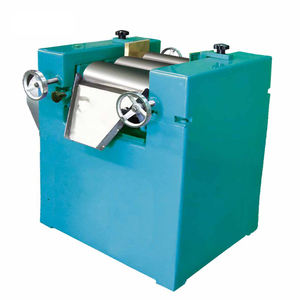
Physically identifying the pump requires situating a significant, elongated, cast metal real estate safeguarded to the engine block with numerous placing bolts. Numerous high-pressure steel fuel lines will emanate from the top of this pump housing, each directed straight to a private fuel injector located on the equivalent engine cylinder. Additionally, low-pressure gas supply and return lines (usually rubber tubes) will link to the pump body, commonly on its sides or reduced areas. The pump will certainly likewise include a mechanical governor link and throttle control linkage attached to it, which converts the driver’s throttle input right into gas delivery changes. A shut-off solenoid will additionally be present on the pump body to help with engine stopping.
Accessing the gas injection pump on the PC200-3 calls for cautious factor to consider of surrounding elements. The hydraulic pump assembly is placed directly to the front of the engine, driven by the crankshaft. While the fuel pump lies behind this about the device’s front, the hydraulic pump and its linked pipes can restrain clear access paths. Furthermore, the exhaust manifold runs along the very same side of the engine (left/port side), potentially creating heat shielding requirements during job. Coolant lines, circuitry harnesses, and architectural elements may likewise need to be temporarily rearranged or eliminated to accomplish sufficient clearance for pump removal or major maintenance. Constantly make sure the engine is totally cooled down before attempting operate in this location because of proximity to warm exhaust components.
(where is fuel pump located on a pc200-3 excavator)
When working with or near the gas shot pump, rigorous adherence to safety and security methods is non-negotiable. The high-pressure fuel system operates at pressures efficient in causing extreme injection injuries; never ever effort to loosen gas line fittings while the engine is running or right away after closure while stress stays. Constantly relieve system pressure utilizing the assigned procedure (usually entailing loosening up an injector line union nut very carefully with safety gear) before detaching any type of gas lines. Avoid dust ingress by thoroughly cleaning the pump and surrounding area prior to opening any component of the gas system. Use only appropriate tools and substitute components fulfilling Komatsu specs. Confirm all connections are safe and secure and leak-free after reassembly before beginning the engine. Speak with the official Komatsu Service Handbook (SEN01237-00 and subsequent updates) for the PC200-3 for thorough treatments, specifications, torque worths, and safety cautions details to this equipment and its fuel injection system. Proper recognition and understanding of the pump’s area and its user interfaces are basic to safe and reliable upkeep.